Electric car
Budget electric car conversion. (continuation)
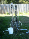
The next step before we put all batteries in, is to sort out the power wiring, as I have mentioned before the power circuit will come my first conversion (Viva) the power circuit was designed so that it can be simply shifted for one car into another without any changes, the principal of circuit is simple and mimics original car power circuit apart that this one is designed for higher voltage and for an electric motor instead of ICE. The principal of circuit: - there is 12 volt battery that connected to the original battery connectors and powers entire car electrical system- like dash board, all car controls like power windows had lamps etc, at the same time the battery is connected to the DC/DC converter via the fuses and set of three relays: one relay is powered from the 12 V and snitches the high voltage from the main battery pack into the converter , another two relays are disconnect the 12v battery negative and positive terminals from converter 12V out terminals while ignition is off to prevent 12 V battery leakage, one relay is controls the controller key switch and also powered by 12v battery and connects the controller to the main high voltage battery pack. All relays are switched on and off by the wire that originally supplies the 12V positive to the alternators rotor coil for exiting the core of alternator and operates by simple ignition key switch, when ignition key is switched on the relays are connect all components, thus 12v battery get connected to the main battery pack through the DC/DC converter and get charged constantly while the ignition on just like the battery get charged from the alternator. There is also one relay that supplies 12 volt to a cooling fan that attached to the traction motor and switches on only when the car is mowing forcing an extra air flow through the traction motor when under load. On the following pictures you can see the components of power wiring that are just shifted from another car and ready for the mounting.  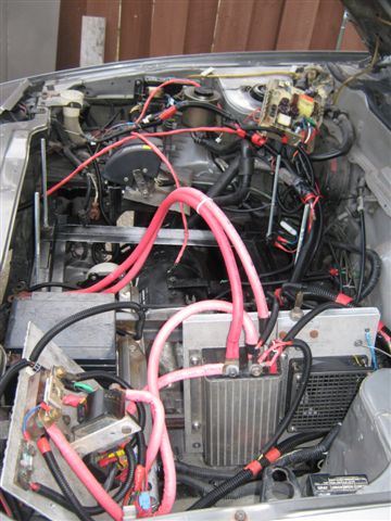 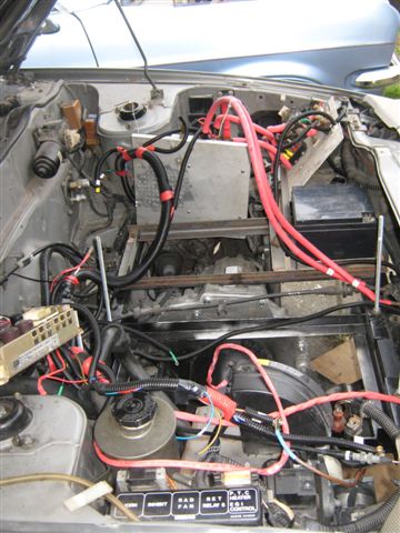 The first component that we decided to install is the DC/DC converter: 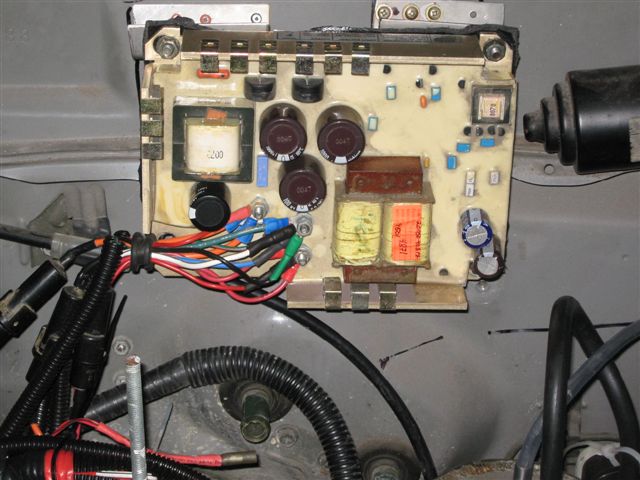 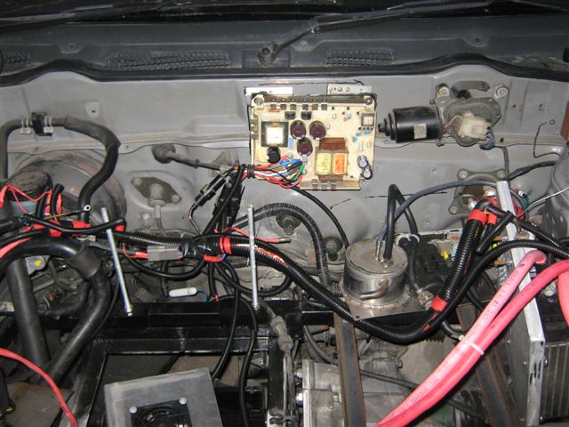 The next components to mount are the vacuum pump and the vacuum vessel, 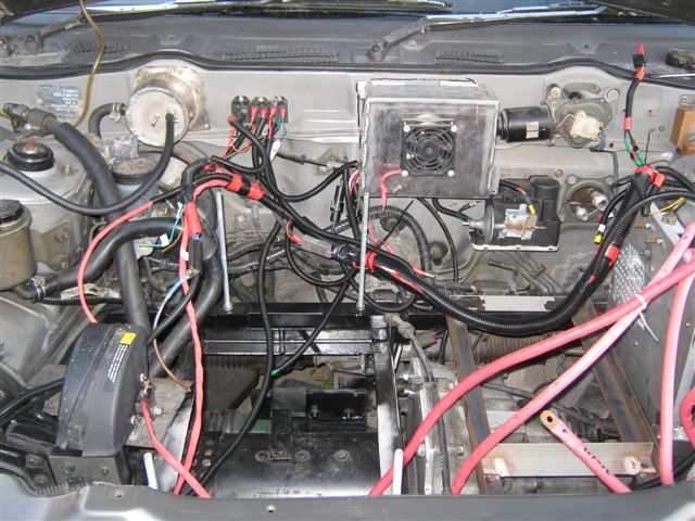 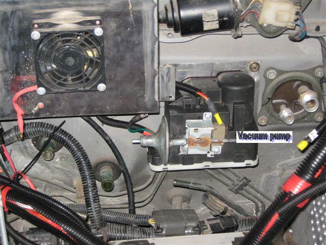 on the picture below you can see the set of relays, two of them are separating the 12V out connectors from the battery when the car's ignition is not switched on, the third relay is the traction motor's cooling fan relay. 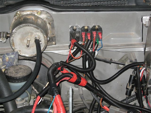 Below is the view of the components location, thus we already know where all components are must be located but still do not know how to mount them: 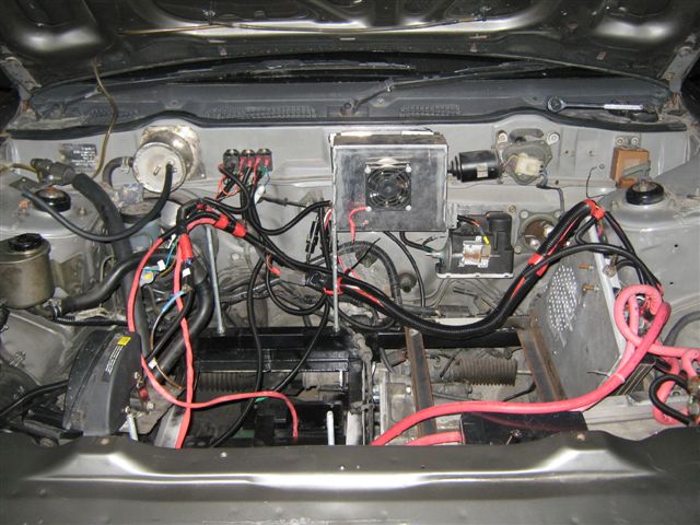 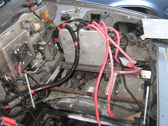 On the pictures below you can see controller and contactor with the main fuse are ready to be mounted onto the car's chassis: 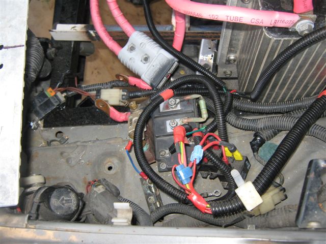 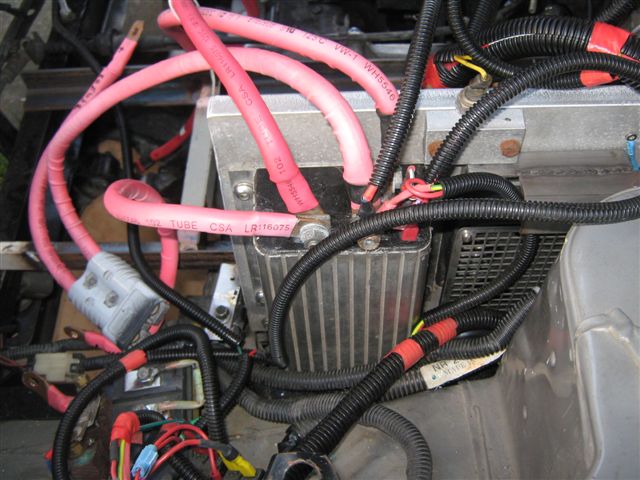 To support our power circuit we decided to use 3.5mm thick aluminium plate that will give a strength to our construction and help to dissipate an extra heat from power components such as main contactor. 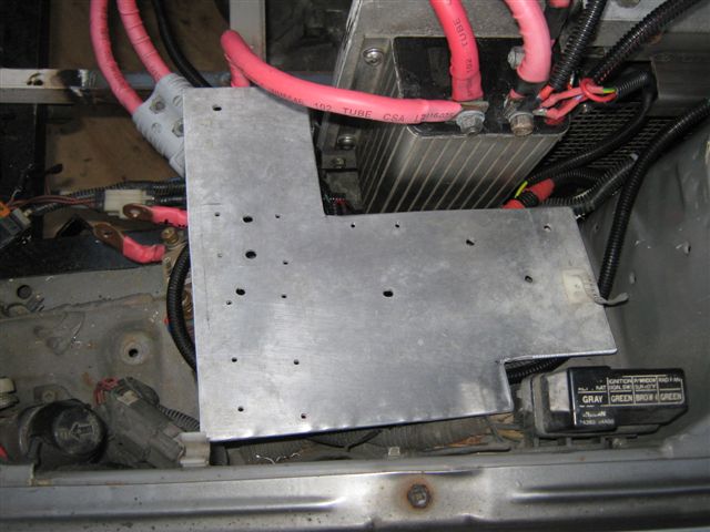 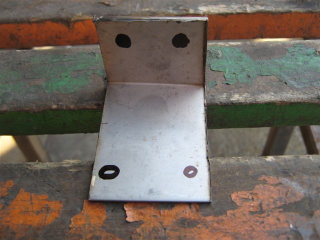 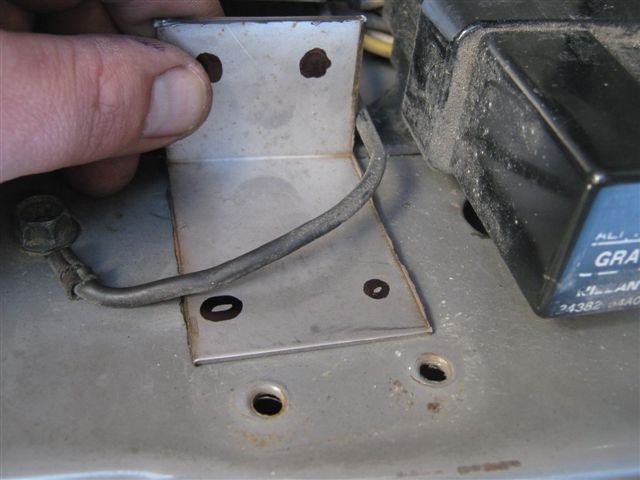 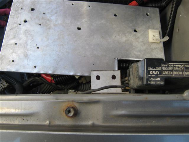 To mount the aluminium plate to the car's chassis I used a stainless steel angle and readily threaded mounting points (there are plenty of them, just use your imagination). 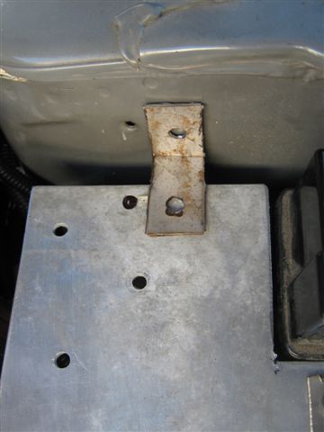 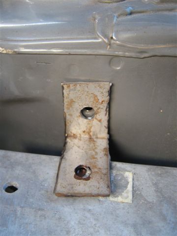 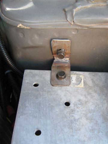 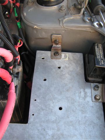 |