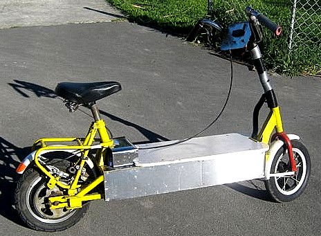
As I had mentioned before - our electric car conversion is budget one, so all components or most of them are really cheap or free, and it is does means that some of those components are not really suitable for our conversion, though most of them can be upgraded, on this page I'll tell you and show via the means of photos of how I did the upgrade of 1204 - 410 Curtis motor controller, how to open it without damaging, without boiling in the pot of water (some silly people do it).
The most important thing about Curtis controllers is that the
"Curtis instruments" company uses the very same design for the variety of their products, all this is dictated by economy, so we can get absolutely similar looking controllers in the same packaging and arrangement with absolutely different specs, and if you open two different controllers you'll find out that everything is similar inside apart from components ratings and number of mosfets they use for the different controllers, for example there is a Curtis 1205 controller that is more advanced than 1204 but the main difference is the size - the 1205 controller just little longer to accommodate more mosfets and one can take the logic board from 1204 and simply install it to 1205 and vice versa, in some models the controller's working voltage is limited by the logic board only - the power board is designed for 48 volts application but the logic board has an overvoltage protection that limits controller to lover voltages.
In our case we will upgrade Curtis 1204 - 410 / 36 - 48V / 225A DC motor controller that is the cheapest of its kind and weakest one, originally designed for golf cars, and not really powerful enough to run the normal size car.
The good thing about this controller is - it can be opened very fast and safe for controller's internal components
replacement or upgrade, it is capable to work with voltages up to 60V and can be easily upgraded up to 500A,
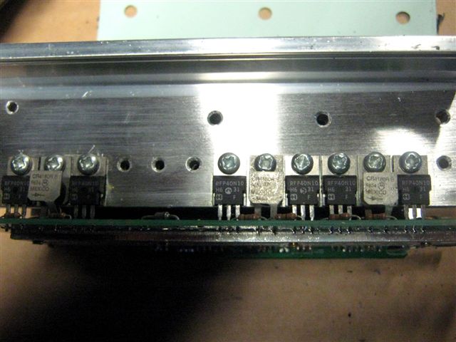
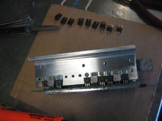
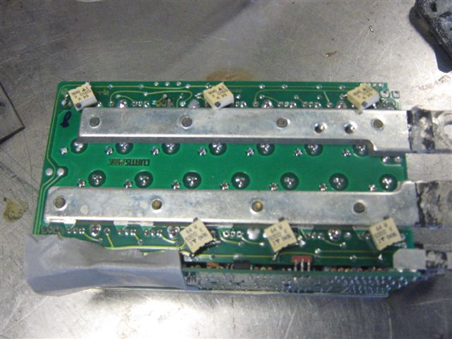
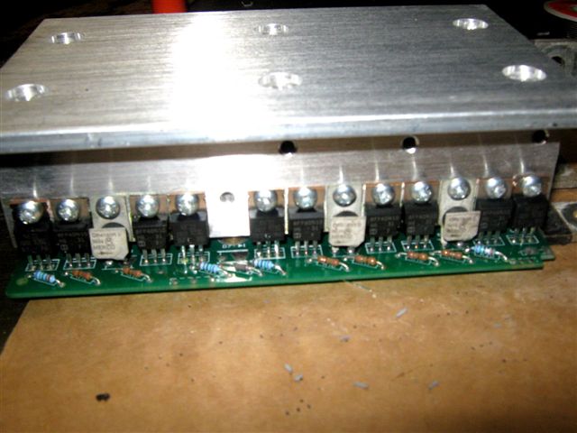
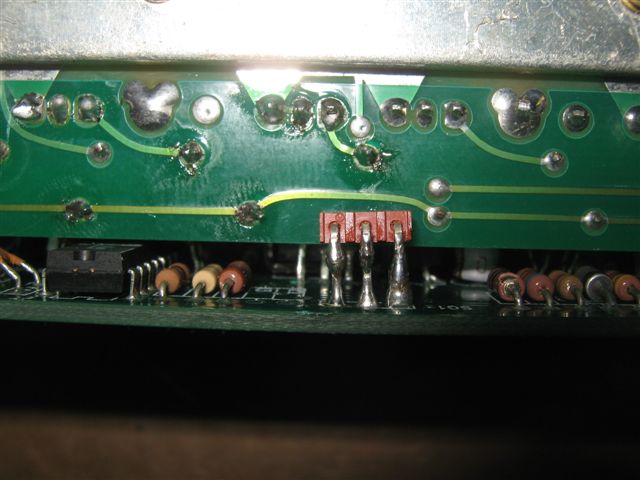
As soon as you'll open this controller you will notice that the controller is heavily lacks power mosfets in its power circuit, and instead of 20 power mosfets that must be installed to the controller you will find only 10, the good thing is - there you can find that all holes already drilled for mosfets mounting and all you need to do is find an extra 10 power mosfets , plus 10 resistors (should match the value of originally installed ones) to drive the transistors gates, then you have to punch the holes for components soldering ion the board (holes are there but filled with solder) and install all the missing parts.
On the pictures below I'll show the steps I taken while upgrading the Curtis DC motor controller.
Below is the picture of Typical wiring diagram for the club car controller.
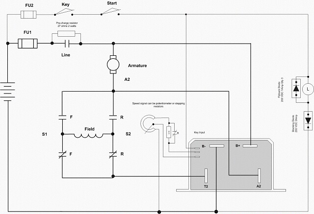
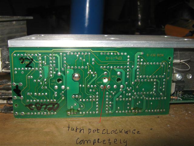
Please note that this controller uses a 3-wire 5K pot. The wiper and one end of the pot is connected to the controller. The second end is tied to B-. Plus some models of this controller are lack the A2 terminal.
It said that the club car controllers are set to 225A and normal controllers of 1204 series are set up to
275A in reality there is no any settings and rating of the controller is determined simply by the number and the rating of mosfets they use - so the more mosfets the higher controller's rating and higher the cost, thus adding an extra mosfet they adding an extra $100.00 to the cost of the controller and as you all understand - all those controllers are heavily overpriced, some companies - like Alltrax are deliberately making their motor controllers non serviceable by filling them up with epoxy resin and any one dollar worth damage inside of controller that buried under the thick layer of epoxy - will result in complete controller replacement, and Alltrax controllers are not the cheapest ones, anyway thanks to Curtis - their controllers are serviceable simple and reliable, plus they providing all necessary data about their products.
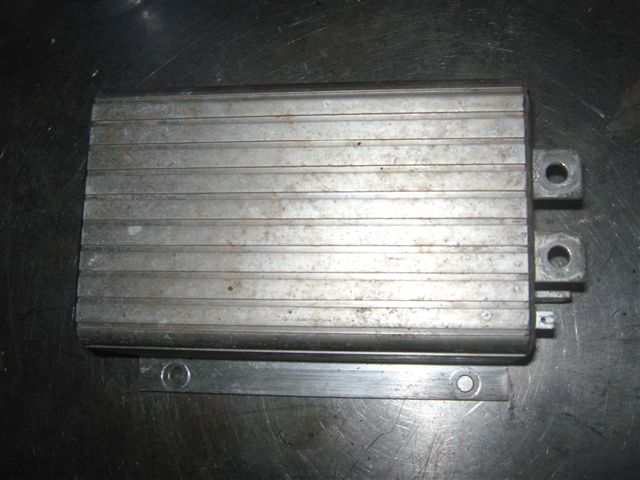
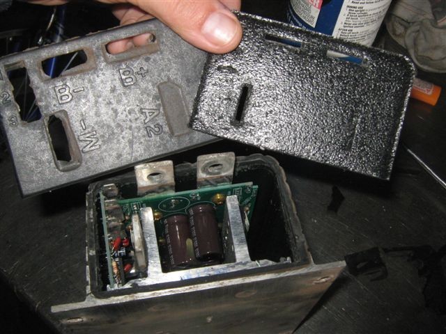
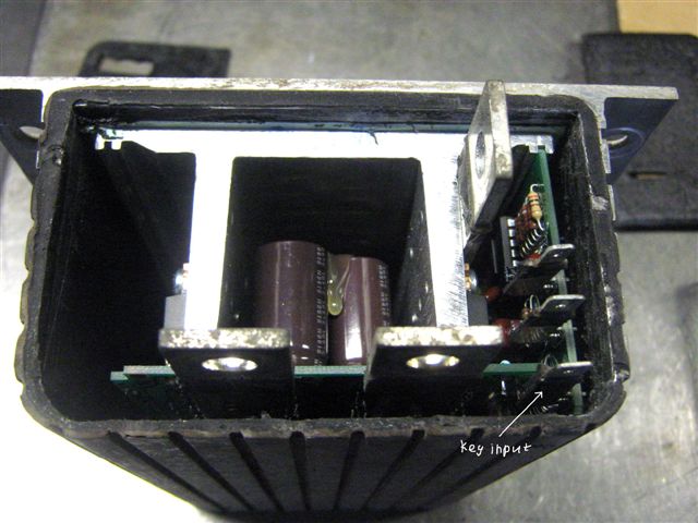
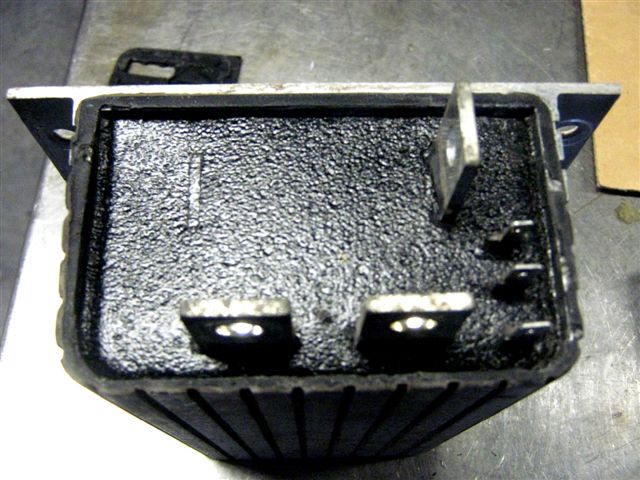
On pictures below is the Curtis controller:
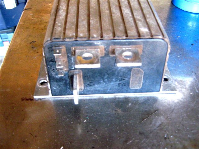  
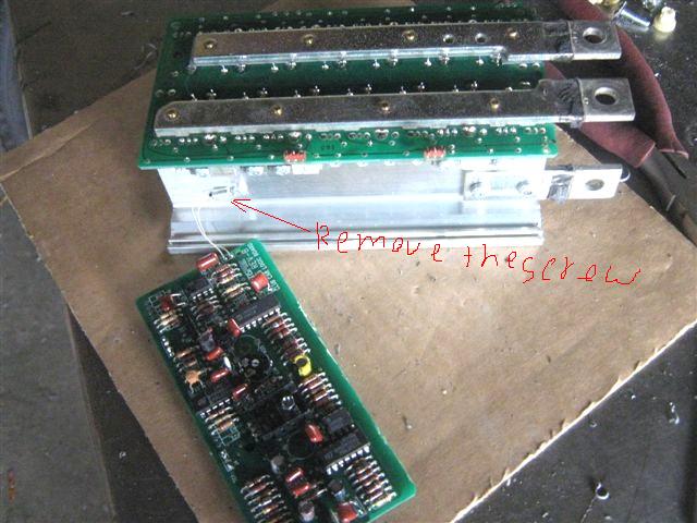
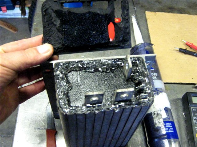
First of all you have to remove the front lid from the controller, to do so you'll need a sharp knife, just cut the lid around and try to remove it without breaking it , once the lid is removed you'll see the silicon hermetic layer and a foam protective layer under the hermetic.
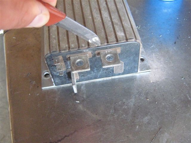 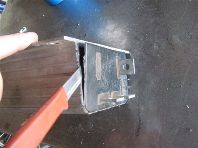 
carefully remove the remains of the silicon and pull out the foam protection.
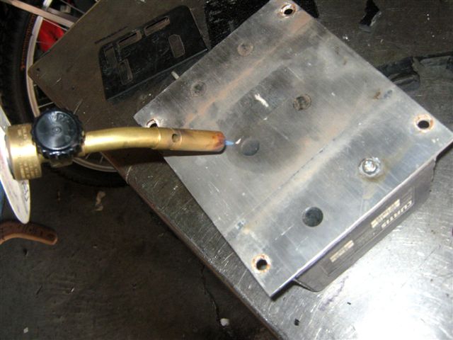
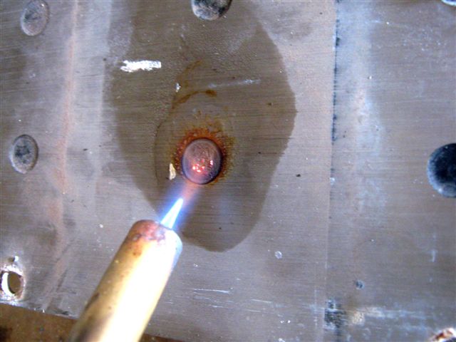
The next step is to remove the epoxy resin that prevents us from unscrewing the screws that are holding the internals of controller in place, so to do it safely just use the propane torch, point the flame to the resin plug and hold for 10 seconds, then use the knife to scrape the resin out, repeat the procedure at least twice the second go will help you to remove the resin from the head of the screw, use a simple screwdriver to remove the screw.
do not worry - the flame will not damage the controller, the whole setup is designed as a big heat sink and has a very good ability to dissipate the heat, but the resin is not that good at heat dissipation and therefore will just disintegrate and become very soft while the controller will remain very cool during complete procedure, thus repeat this procedure with every single epoxy plug, the total time to take whole controller apart is around 20 minutes.
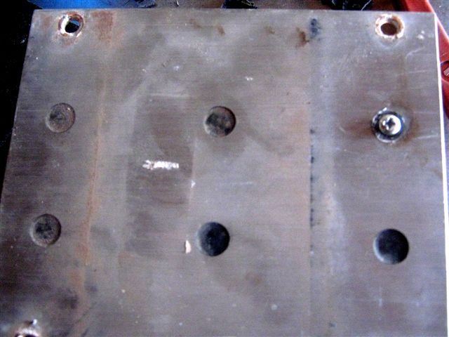  
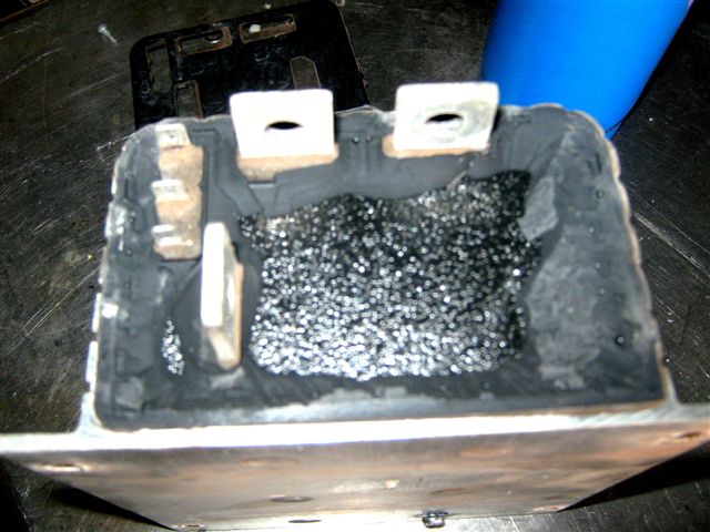
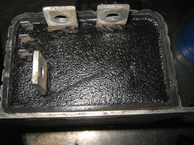
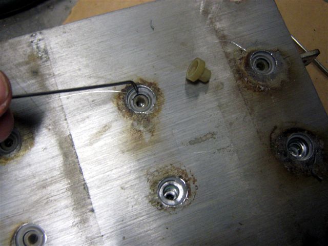
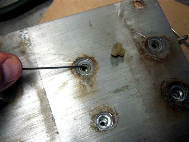
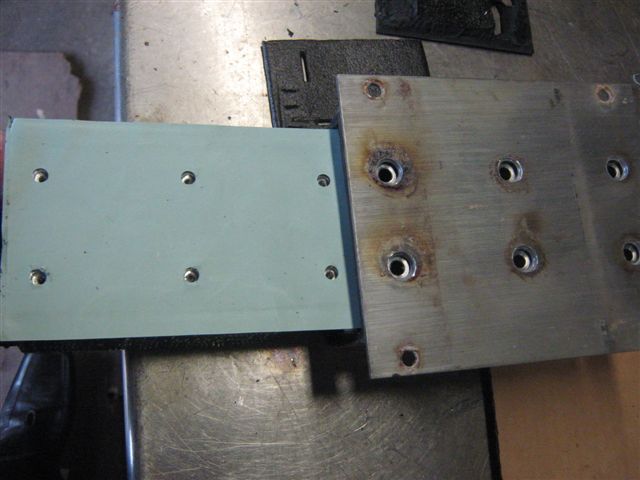
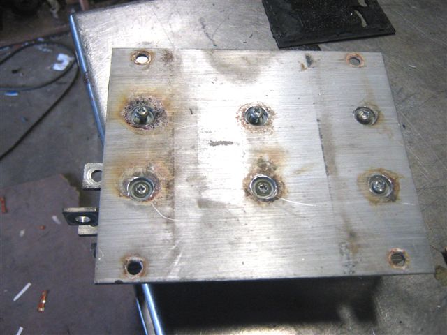
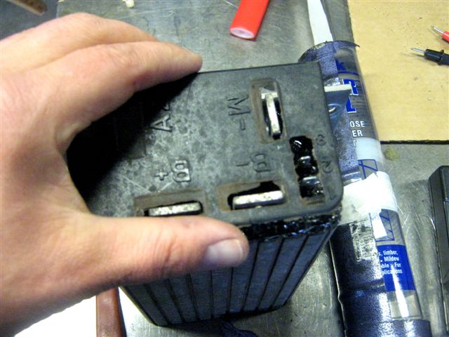
Now we can remove all screws from the bottom of the controller, please note that under the screws there are plastic spacers ( insulators ) that prevent the controllers internals from electrical contact with the outer shell of the controller, and we need to remove them first and only after the spacers removal we can pull out the controller board.
Thus for the plastic spacers removal we need to clean up the holes above the spacers from the remains of epoxy resin that keeps spacers glued in their slots.
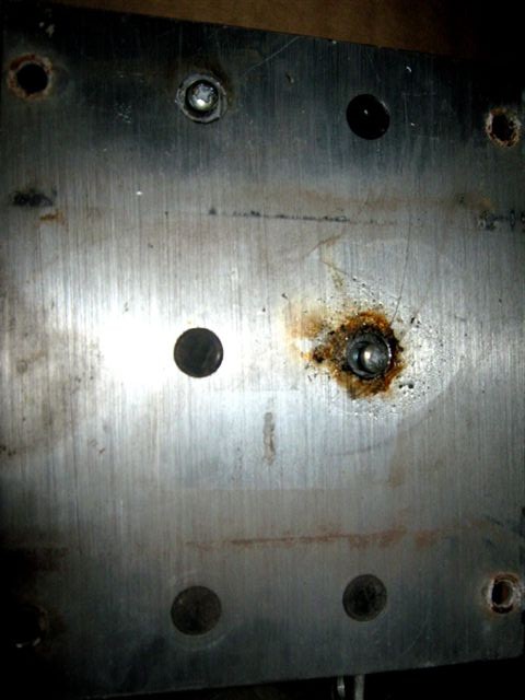 
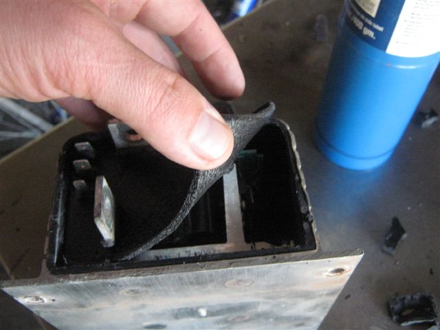
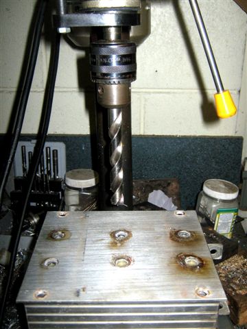
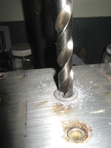
for cleaning the remains of resin from the slots I used the flat tipped 13mm diameter drill bit, and please be careful not to drill through the plastic spacers. Once the epoxy removed from the holes completely you can easy pull the plastic spacers out with a small metal hook.
  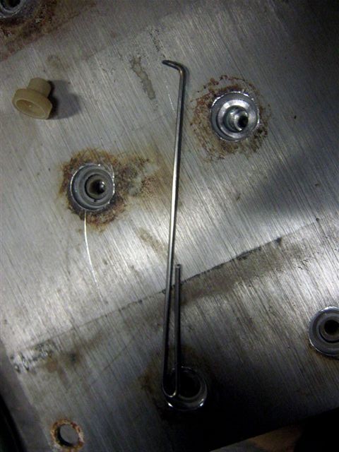
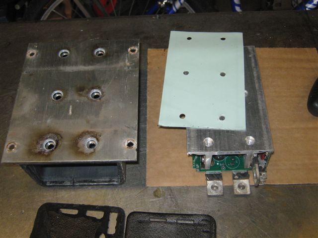
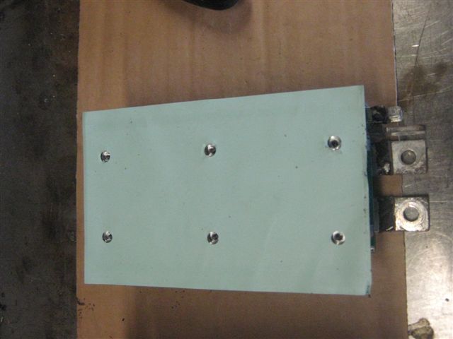
In case to remove the power board of the controller make sure that all the spacers are pulled out.
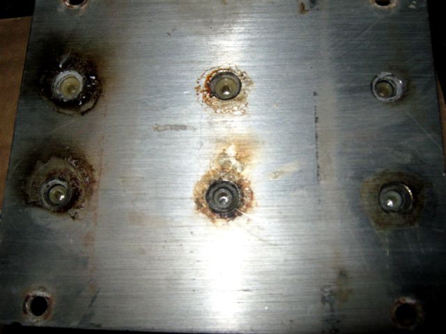
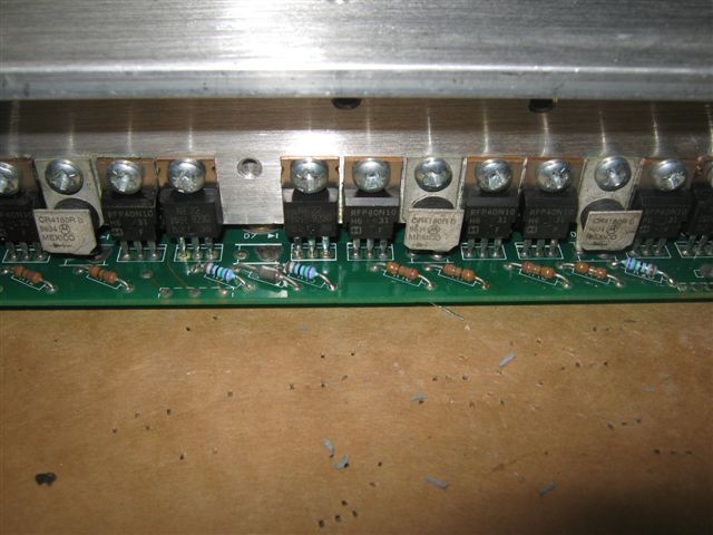
Below is the example of how to remove the power board, please be careful with silicon heat conductive insulator. Plus there you can see the Curtis amperage rating setting - they just forget to install a few mosfets, also there is the view of the logic board that need to be temporary removed as well, for our upgrade.
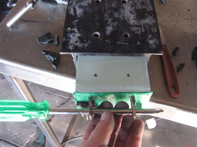  
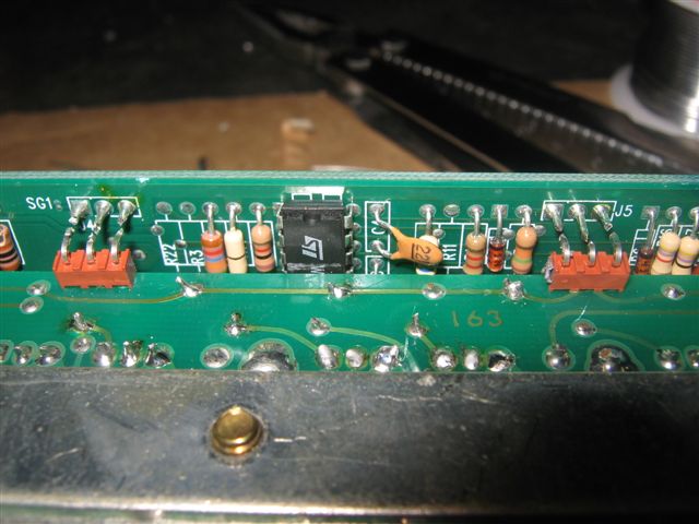
Do not unsolder the logic board, (the solder they use is hard enough to damage the board before the solder will melt) just cut the connections off.
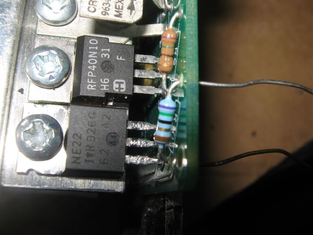
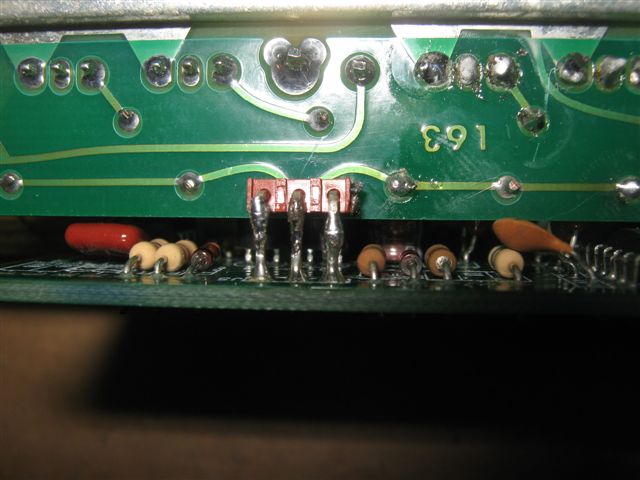
As you see the total of 9 transistors must be added to the controller to perform at full potential, plus you will need to add 9 resistors as well the same way the original ones installed, plus the resistors must match the value of original ones, in my case there were 75ohm resistors, the transistors for this project I cut from Curtis 36V 600A Sepex controller (approximate value 75V / 60A), but for the previous project I used IRF540N 100v/33A mosfets and sealed trimpots instead of resistors and this particular controller is still performing ok after two years of exploitation.
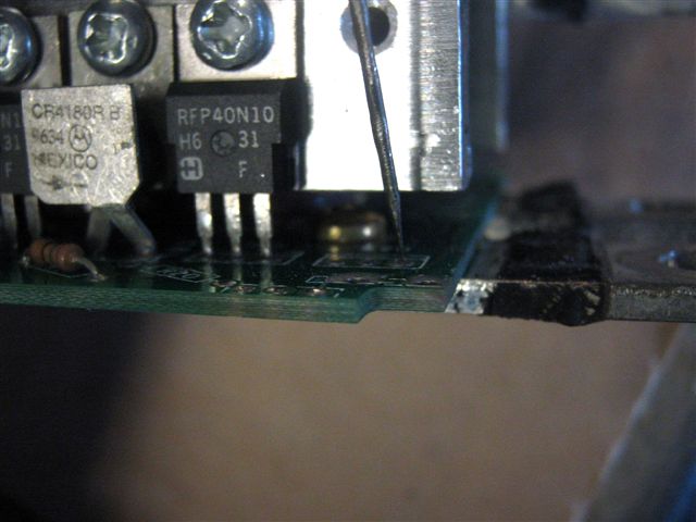
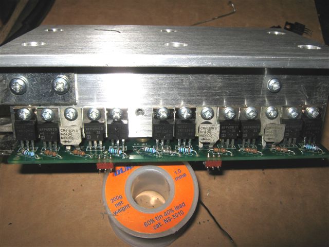
On the pictures below you can see the controller's power board is ready for upgrade and also you can see the needle like steel wire, I pointed this needle to the soldered point where originally a tiny hole for the component installation should be, and while applying a slight pressure to the needle, I am pointing the 80w soldering iron at the opposite side of the board just for a second and this is enough for the needle to punch the molten solder through and make a perfect hole for the component mounting.
Please note that I am not adding any additional diodes, as practice shows - the ones that already installed are capable to handle the load, so there is no really need for any additional ones (this project is for series DC motor).
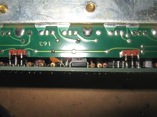
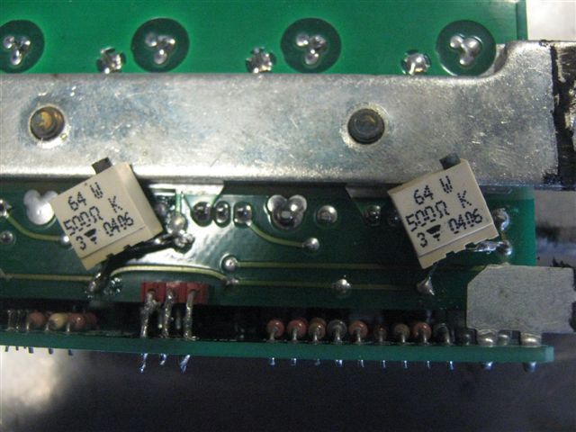
Here you can see an example of trimpots application, - in some cases it is impossible to get the right components and the only way to make the controller work is to use what you can find around, plus trimpots can be setup to any value.
When all the holes for the components installation are ready to accommodate all resistors and transistors - just insert the legs of transistor to the holes and before soldering apply the screw to hold the transistor in place, then insert the leads of a resistor solder and cut the excess, insert and solder each component one after another - making sure that no component was missed.
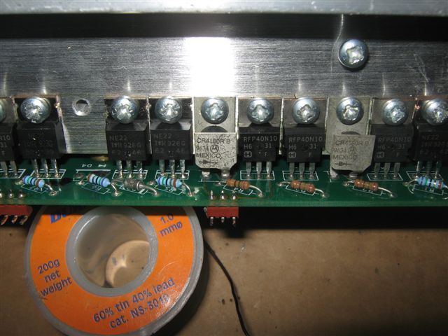
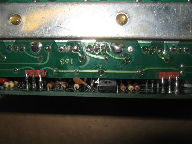
Here you can see both sides of the controller with all the components installed, the blue resistors are corresponding with newly installed transistors, so we added 9 transistors all together:
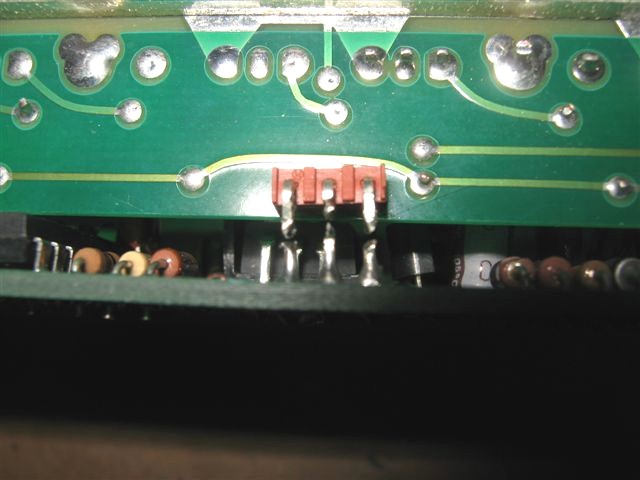
The logic board is inserted into its slot and leads are aligned for soldering.
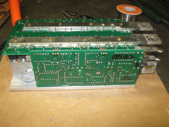  
The logic board is installed and the controller is ready for the test run.
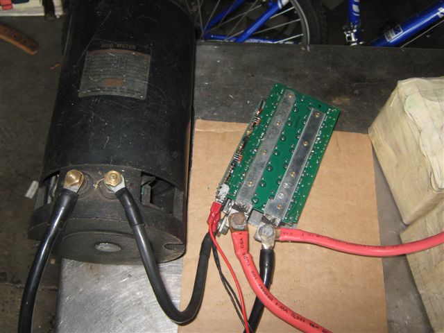
On the bench first
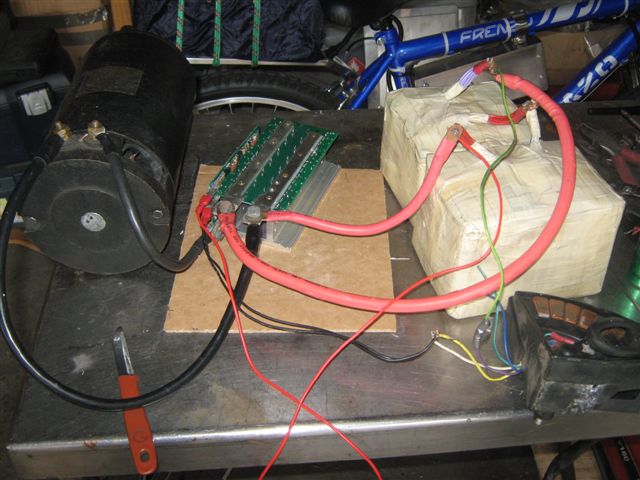 
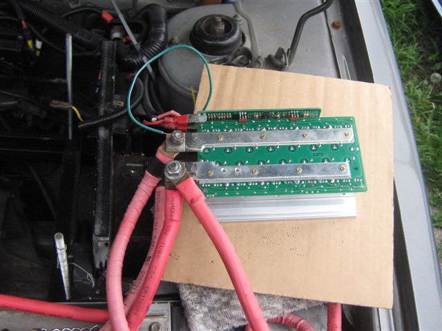
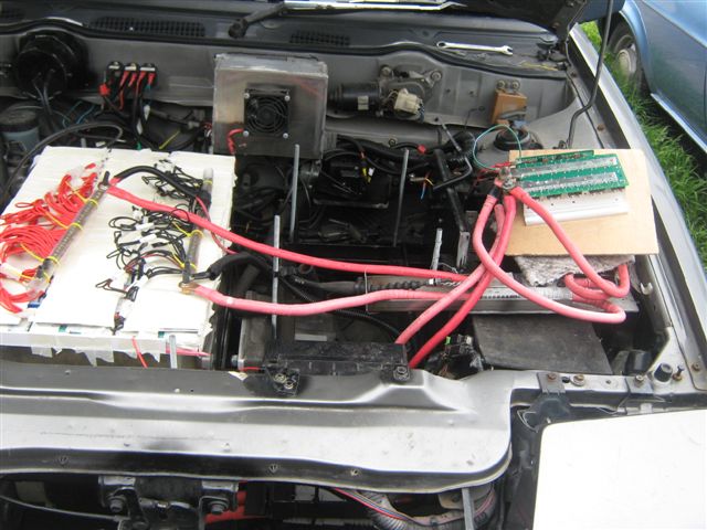
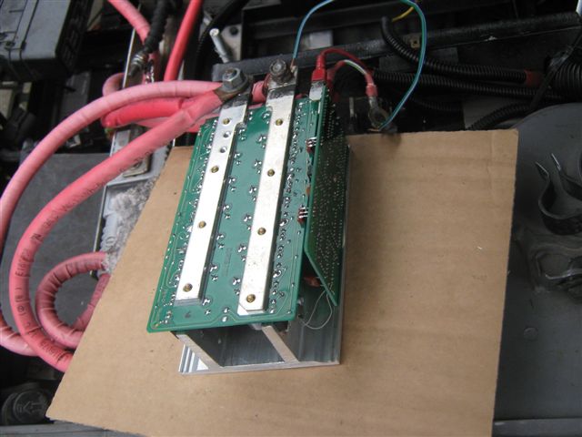
and on the car second.
The controller is tested and appears to be working ok, so now we can start a final assembly.
Apply all the plastic spacers and screws, tighten all screws and check for the electrical insulation - there must not be any electrical contact between the power board and protective shell of the controller.
The controller is electrically tested and now we can place the foam protection and the front lid, now very important note -
apply the heat shrink insulation on the key input terminal and make sure that the silicon adhesive that you'll use for the front lid gluing does not touches the Key input terminal ( most of adhesives are remain slightly conductive even after complete drying, just enough to make your controller to make you a headache), otherwise you will get your pot input shortened with positive key input and result is high revs of the electric motor when the pot is pressed to get a low revs and you'll get a sudden acceleration.
Now apply the glue and place the front lid where it is belongs.
Do not forget to apply some silicon to the screws on the bottom of the controller for protection against moisture.
on pictures below you can see the old controller and the newly upgraded one that will replace the old one.
Finally controller is ready for performance.
Good luck with your controller upgrade.
|