|
|
|
|
|
Electric car
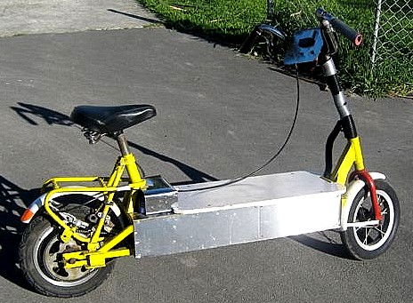
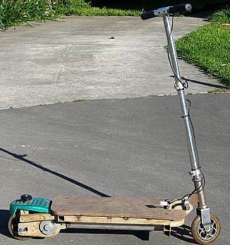
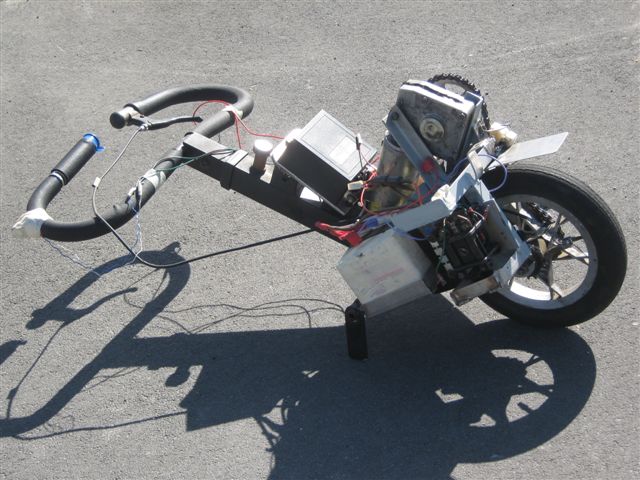
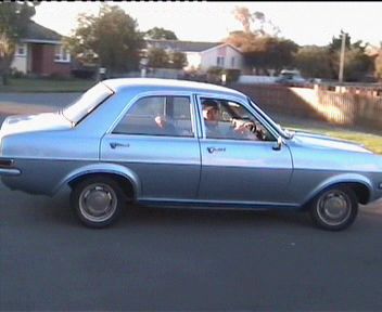
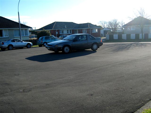
Electric Vauxhall Viva. | Electric Nissan EXA. | Custom made NI-MH battery. | Ride on electric Nissan. | Electric Nissan test drive. |
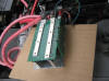
Click the following link to find some information about Curtis 1204 - 410. 36 - 48V/225A DC motor controller upgrade.
 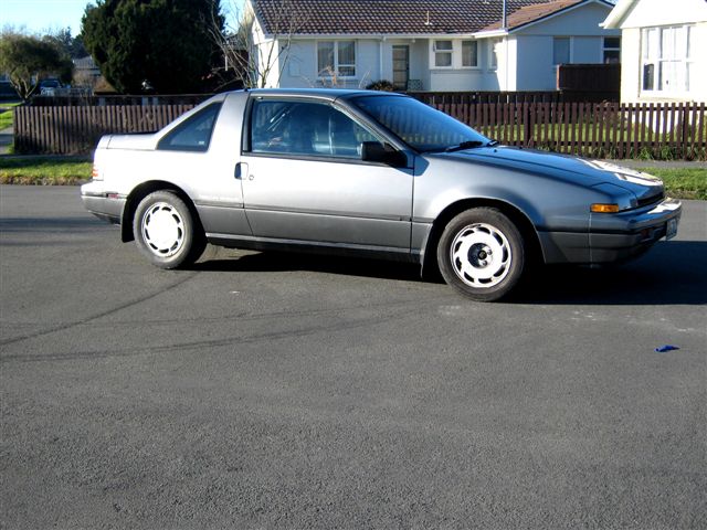  |
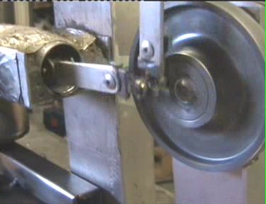
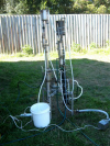
Budget electric car conversion.
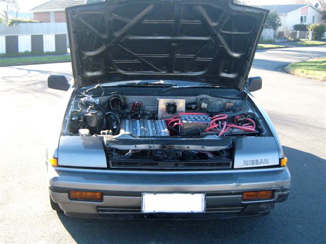
| The car that you see on the video above is no longer exist, this car was a test bed for the parts and battery arrangement that was applied to this project, the Viva was tested for one year and now we decided to build another electric car that will be based on the same design and principal that was used for Viva Electrica minus all the mistakes of Viva design and plus some extra things: water heating system for interior heater, plus power steering, and also we planning to install the range extension battery pack that is going to be a different chemistry from the main NI-CAD (flooded type) battery. the extension pack will occupy the space that originally occupied by the petrol tank and will be engaged with the main pack only during vehicle movement. This new electric car project is based on the same principal as the previous budget electric car project, the parts that will be used for the project are mostly came from a junky yard, and off shelves of hardware stores, so the car's ingredients originally are not meant to be used for the electric car and because of that they are relatively cheap and available. The whole conversion is done under the blue sky and in the small garage environment with the help of imagination and a few common tools, the car's power circuit is came from the previous conversion, though all mechanical work in needs to be repeated again; such as adaptor plate and motor and gearbox coupling, power unit installation, power steering design and installation, heater design and installation and so on and all of this is going to be done on a budget in a simple garage. The donor car is Nissan EXA chisel like small sport car with front wheel drive. 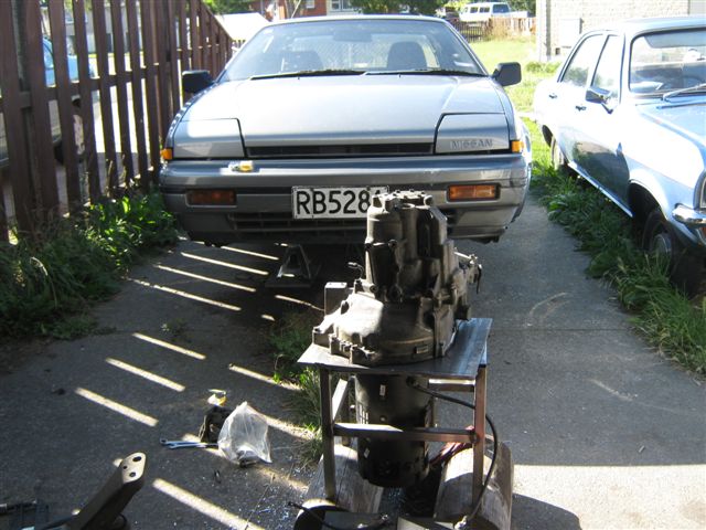 I will not cover the internal combustion engine removal from the car, I did it from underneath the car, I will mention just few tips: do not damage an original wiring and try to remember where the alternator connection, battery connection. Collect all bolts and nuts that you are removing from the car, do not dispose or sell original engine until you are finished installation of electric motor , because you may need either belt or pulley or engine mount, even extra bolt. Collect all engine mounts and see if you can use them for your conversion - it can save a lot of your time and money - so try to use as much as possible parts that you can harness from the original power unit. Adaptor plate and motor/gearbox coupling. To couple the electric motor and gearbox we decided to make a straight spline and avoid any clutch, because we hoping that the car will be comfortably moving around on the third gear automatic like where is no gear shifts will be necessary apart from reverse, plus we still got some options of lower gears for heels and for conditions where a torque will be required. thus for this purpose we decided to use the original clutch plate that came from our IC Engine and the oil pump that was attached to the electric motor while on forklift (the motor originally came from a forklift) so we removed the central plate from the clutch assembly and main shaft from the pump - the clutch plate is matches the gearbox's central shaft and the pump's shaft is made for the electric motor so we already have got two ends for our spline, 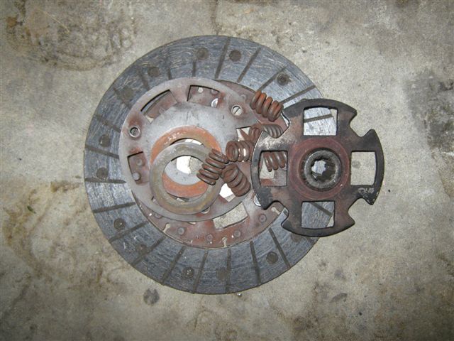 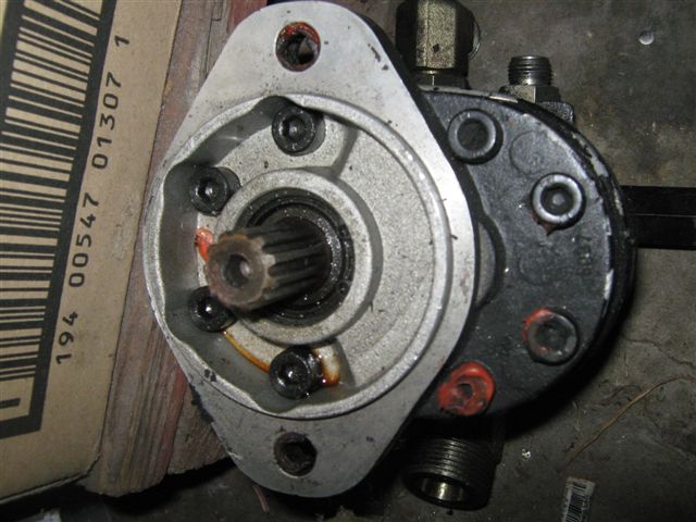 all we need to do is ask the machinist to machine down some metal excess make some kind of metal bush and assemble the spline.  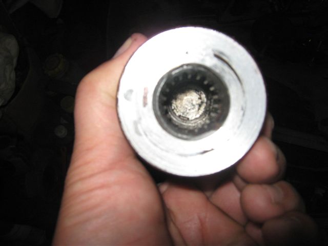 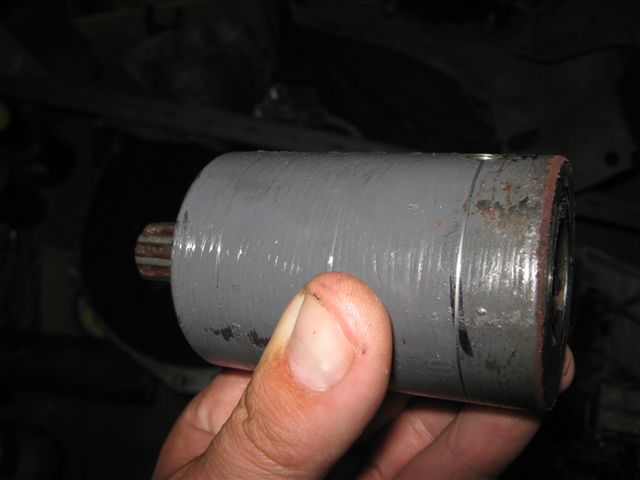 Please note that before of making the spline we measured the distance from the gearbox shaft to the shaft of electric motor plus the thickness of the adaptor plate, so get the aluminum plate handy and prepare everything you can for the conversion. On pictures below you can see the plate with schematic draft of gearbox shape on the metal, to do so we took the original metal plate that usually installed in between the engine and gearbox, placed it on aluminum plate and draw the shape of gearbox's face, the drawing does not need to be absolutely exact, it is done to give an idea of the adaptor plate dimension - to find the approximate location of the center and to cut unwanted metal. When you are found approximate location of the center (measure the distance from different points of the face of gearbox to the centre of the shaft) then cut the hole that is bigger than the diameter of the spline.  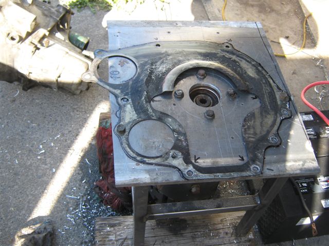 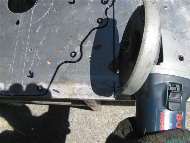 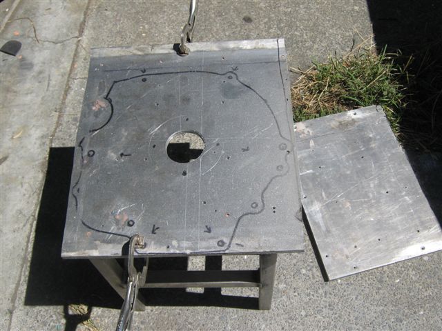 Now we need to drill the holes for the bolts that will keep the adaptor plate and electric motor together, to do so we covered the electric motor's face with the tiny layer of CV joint grease and placed over it the white sheet of paper and get exact location of holes in respect to the motor's face, plus made additional measurements of distances between holes centers, then transfer our measurements on to be the adaptor plate and drill the holes, thus if you are place the paper with printed motor's face over the adaptor plate the holes on paper and plate must match each other. For best results use a drill press and make small diameter pilot holes first. 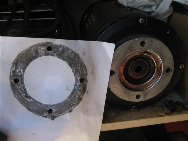 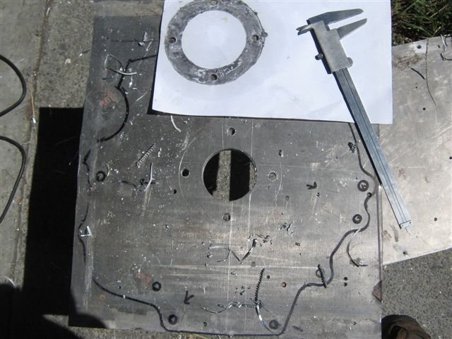 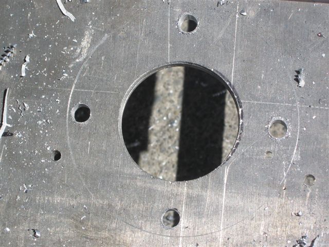 Now when all holes are drilled we are attaching the adaptor plate to the face of electric motor, and on pictures below you can see the plate mounted to the motor. 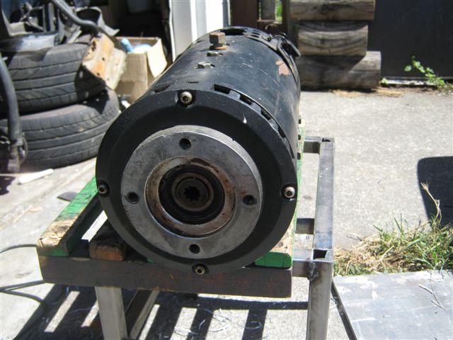 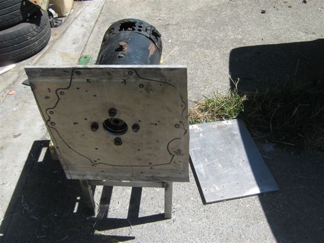  So the plate was bolted to the motor and fits perfectly, the next trick is to place the motor into the frame as on a picture below, the motor is actually hangs on a plate and the top of the plate is forming some sort of table, so we can place the gearbox over the motor easily. Thus the next step is to insert the spline into the motors shaft... Please note that the gearbox's end of the spline is drilled little dipper than needed so we have some extra depth inside the spline for the shaft to go in in case our adaptor plate is thinner than it is so the shaft will go dipper and to prevent the spline from moving along the shaft we inserted a spring into the spline just us on a picture below. 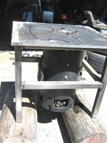 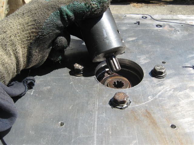 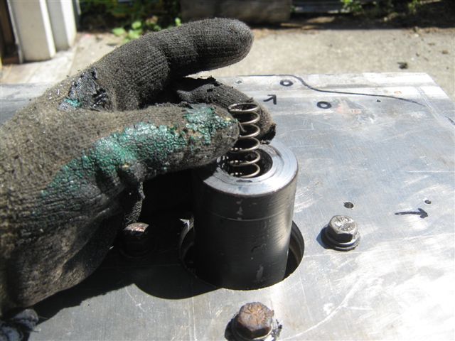 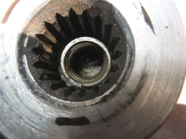 So our spline is on place and this is time to install the gearbox. The original thin metal plate that was installed between engine and the gearbox is placed on top of aluminium to be adaptor plate, and the gearbox is placed on top of thin metal plate where we are matching all the holes of gearbox and the thin metal plate. Please note that the gearbox is simply lays on the flat surface of the aluminium plate and when both shafts (motor and gearbox) are in the spline the system is self centring, plus while on a flat surface there is no forces that will tend to move the gearbox off centre. to mace sure that the gearbox is installed ok we attaching the 24V battery pack - forcing the motor to rotate the shaft of the gearbox, make sure that the gearbox is on neutral gear. If everything is normal then no vibrations and funny noises should appear, the most important thing is spline that must be manufactured by professional with the implementation of precise equipment - so the spline the important and precise link between the gearbox and the motor. 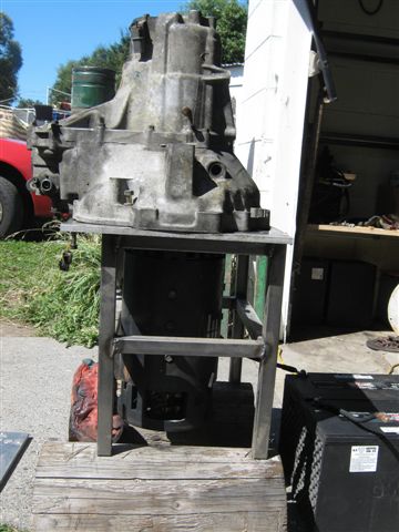 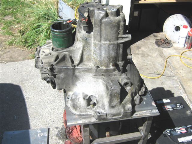 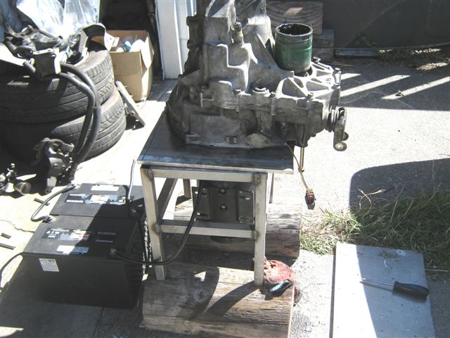 The next step is to secure the gearbox on the plate in this position, in this case we use a couple of clips on diametrically opposite sides, once the clips are applied we checked manually that gearbox and motor shafts are rotating freely and also tried to spin the motor with the help of small battery pack - to make sure that the gearbox is still inline with the motor.  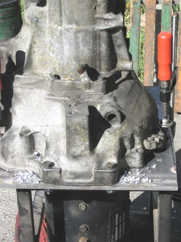 Now we starting to drill the holes in the adaptor plate and we use the existing mounting holes on the gearbox as a pilot holes, the diameter of holes in the adaptor plate is the diameter of bolts we are going to use. In our case we will use the original bolts that were used once to keep the gearbox and ICE together, plus we bough the set of self locking nuts and few extra bolts, originally the bolts are were screwed into the ICE block so that's why we need those nuts. Once we are drilled the hole - we straight away applying the bolt and nut and tighten them to keep the assembly secure, so we repeat the operation until all holes are drilled and nuts plus bolts are applied. some can say that all those holes are not going to be perfectly centred, yes and because of that the next time you are try to couple the gearbox and the motor together - all bolts inserted into the imperfect holes will keep the assembly in perfectly right position that was chosen before drilling.   Ok, all holes are drilled and bolts are inserted into their places, so this is time to undo all the bolts and to remove the gearbox. On picture below you can see the gearbox is removed and original thin metal plate is tighten to the adaptor plate - thus we can drill the holes that were unreachable while the gearbox intact with the plate. 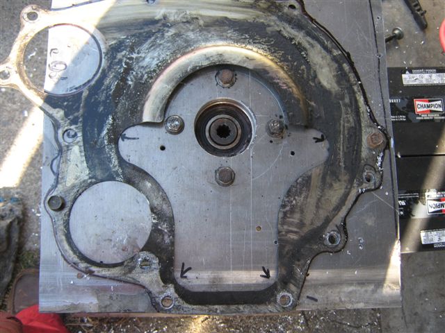 On the picture below you can see the adaptor plate is removed from the electric motor's face and original metal plate is still attached to the adaptor plate - in this case the thin metal plate is used as a guide to cut the hole for the drive shaft to go through.  When all holes are cut we can start to remove some metal excess from our adaptor plate, in our situation we used a simple angle grinder. 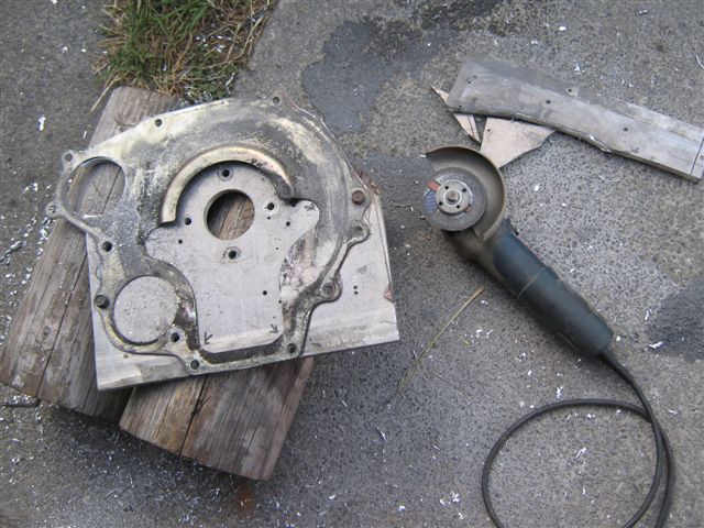 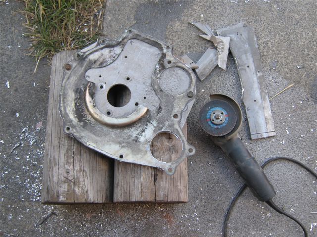  On pictures below you can see the final touch up of the adaptor plate, the steel plate on top is used as a guide to cut and polish edges and finally our adaptor plate is finished and ready to be installed and become the medium between the electric motor and the gearbox.  The adaptor plate is finished and we begin final installation of the plate. First of all the plate is bolted to the face of electric motor, then motor is turned face up with support of two wooden logs - so it will be easy to bolt on the gearbox and re move the complete assembly from supports. The original metal plate is placed on top of aluminium adaptor plate and will remain in between the motor and the gearbox, the spring is inserted into the spline, the gearbox is evenly placed over the adaptor plate and bolted all around.  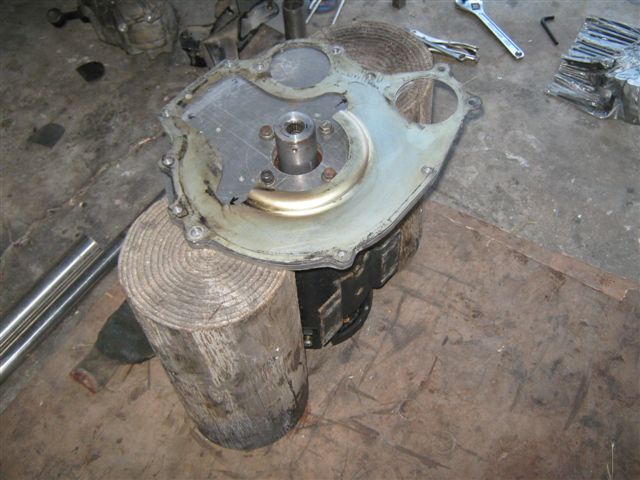 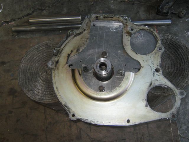  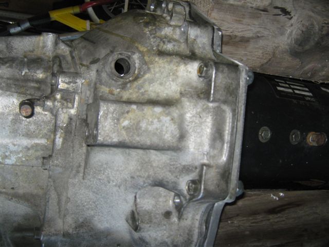 The electric motor and the gearbox are coupled together and next problem to find the solution for is how to secure the drive shaft that originally was attached to the engine side.  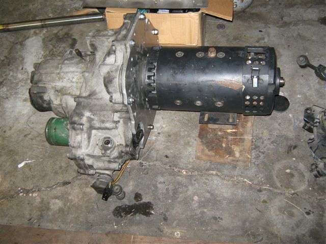 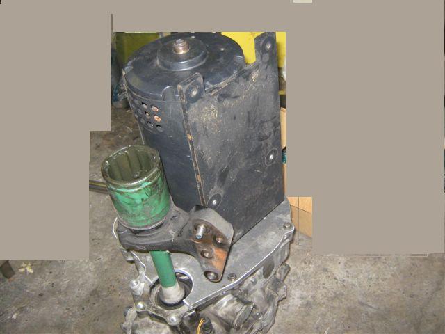 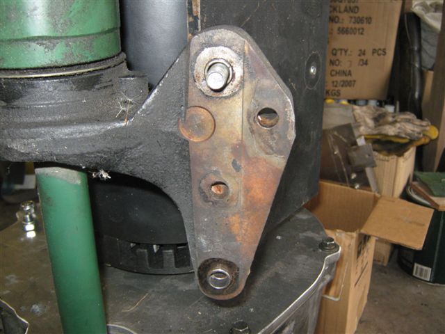 Below you can see that we decided to use a thick flat piece of metal to make a plate for the shaft's support, later we will weld some extra metal top this piece to mimic the original mounting, thus the low part of metal plate will be attached to the flat plate that will hold entire motor and the top part of shaft support will be bolted to the electric motor. 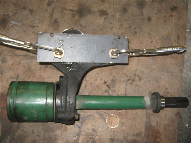 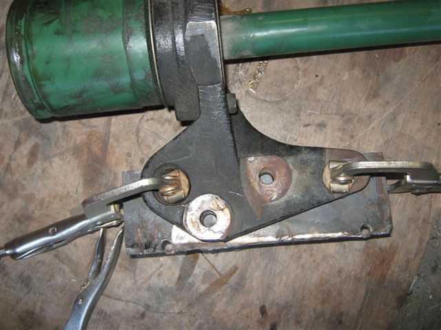 On pictures below: the plate attached to the shaft support by two clamps and holes on original support plate are used as a pilot holes to drill the same diameter holes in our thick metal plate, once two holes are drilled, we replacing the clamps with appropriate size bolts to secure the plates together and drill the rest of holes, when all holes are drilled we make some bigger diameter drilling to form a housing for small bushes that inserted in both plates and preventing plates from sliding.  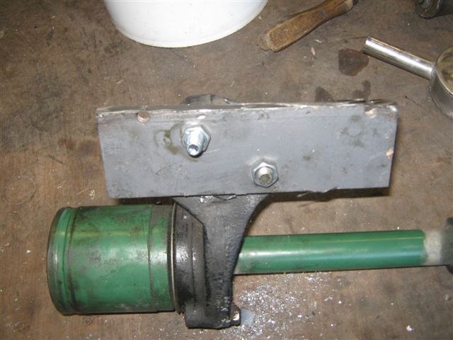   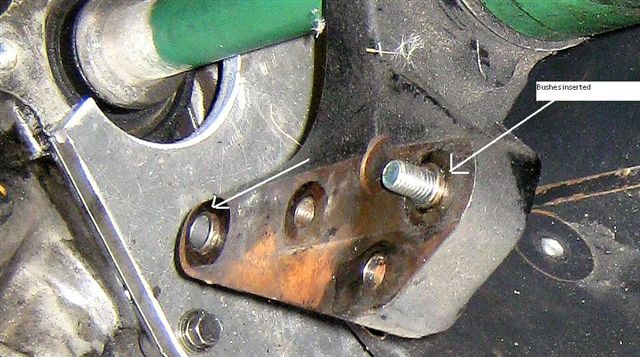 On the pictures below you can see the plate is bolted to the bearing support. 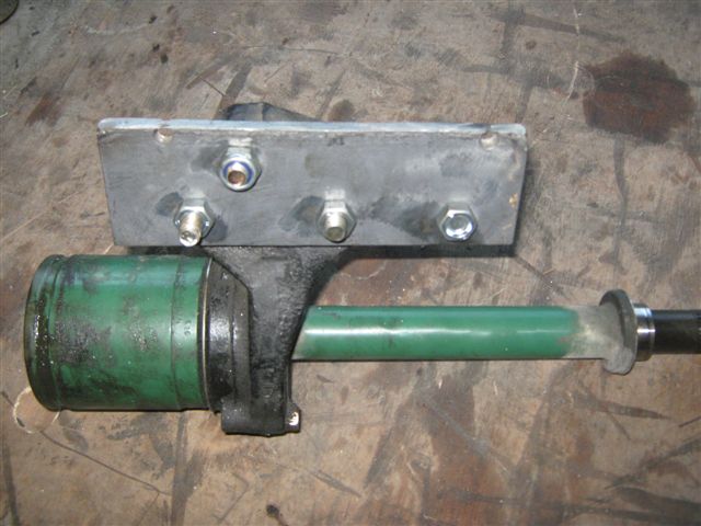 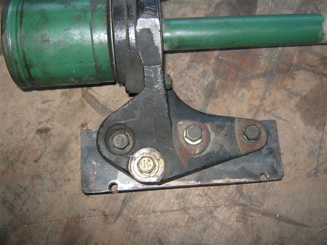 When the plate is finished the shaft is inserted into the gearbox, with the plate attached to the shaft's bearing support, the electric motor has a threaded holes around stator, this holes are used for motor to be easy removed or installed and special hooks can be screwed up into this holes, so we decided to use this hole as one of the mounting points for the shaft's bearing support, the plate that is bolted to the bearing support is not in line with the top bolted to the motor plate so we will make the support out of multiply pieces. The parts of construction are tick welded together just on place to insure the right alignment, then removed from the motor and the gearbox and properly welded together.  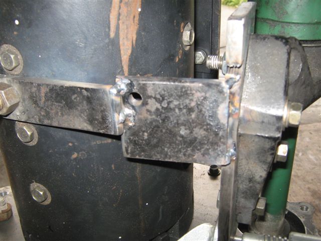 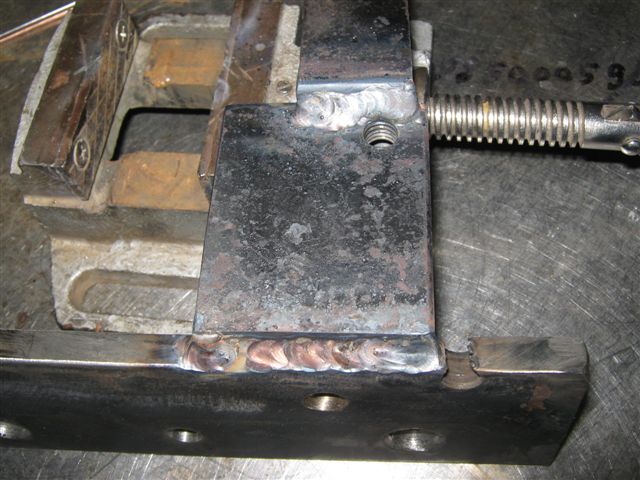  Below you can see how the support is looks like, the mounting point on the top of the motor is not enough, the support must be absolutely solid so we decided to add some extra strength to our construction, 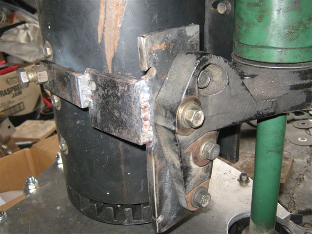 so we will weld an additional plate to the support that will connect the big motor plate with support of the bearing. 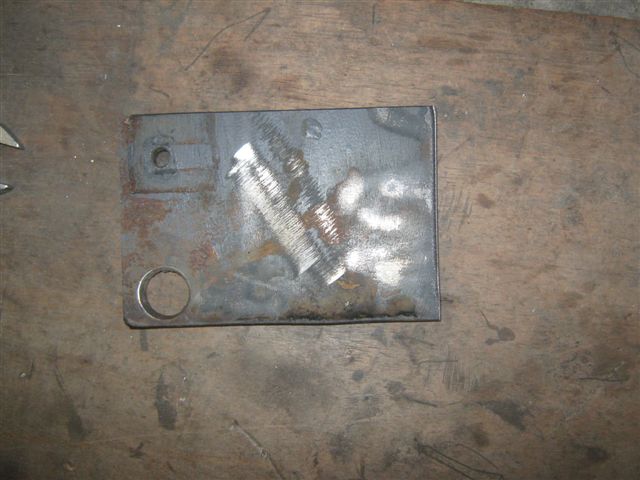 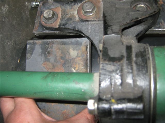 The plate is measured and tick welded on place to maintain the alignment of construction ( note - newer connect the welding leads to the motor or gearbox - the leads must be connected to the parts that being welded, in our case : the plates). 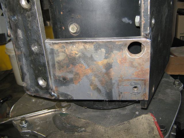 When the plates are tick welded to each other the all construction that includes the big metal plate that bolted to the motor is removed and all joins are welded properly.  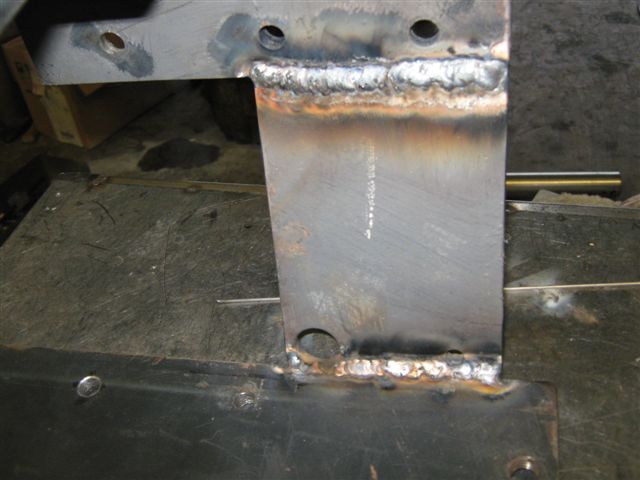 The complete support is bolted back to the motor, the construction is forming the kind of box section. 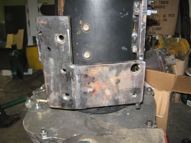 Here you can see the support from different angles with the axle in place. 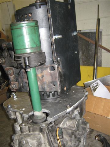 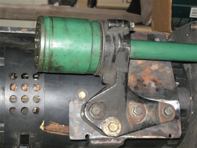  the electric motor is bolted to the adaptor plate via four bolts and also there is the plate that bolted to the motor and supports the axle and will be attached to the engine support that will support the rear of our power plant, so we will get some extra force in the point of the motor and the gearbox connection, thus we decided to add an extra mounting point that will connect the bottom motor plate and the gearbox, to do so we will make a metal angle that will be welded to the bottom motor plate and bolted to the gearbox. First of all we cut appropriate pieces of 10mm thick metal, found the right position of the angle and drilled the hole for the bolt top go through. 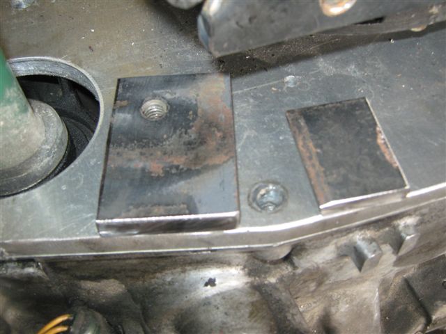  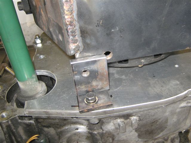 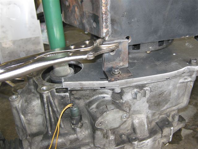 Then tick welded and made sure that the hole in the angle is matching the hole in the adaptor plate, after that we welded the angle completely. 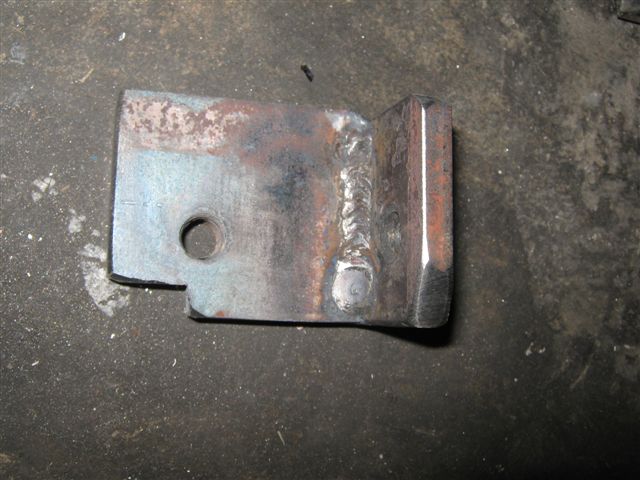 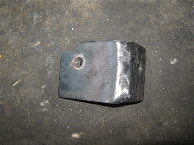 When the angle is finished we bolted the angle to the gearbox and welded the angle to the motor plate, please note that while angle is welded the metal will expand due to heat and after the the cooling and contraction there will be a gap between the angle and the adaptor plate, so to keep the construction aligned use a flat metal spacer between the bottom of the angle and the adaptor plate. 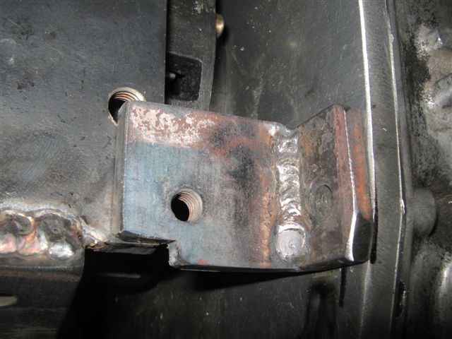 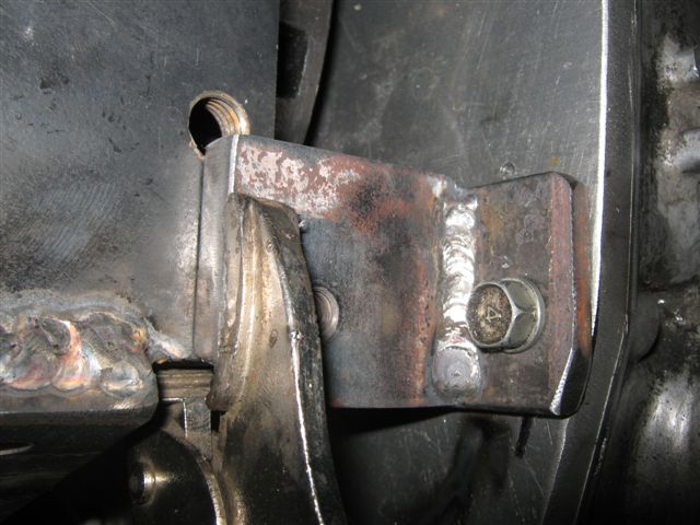 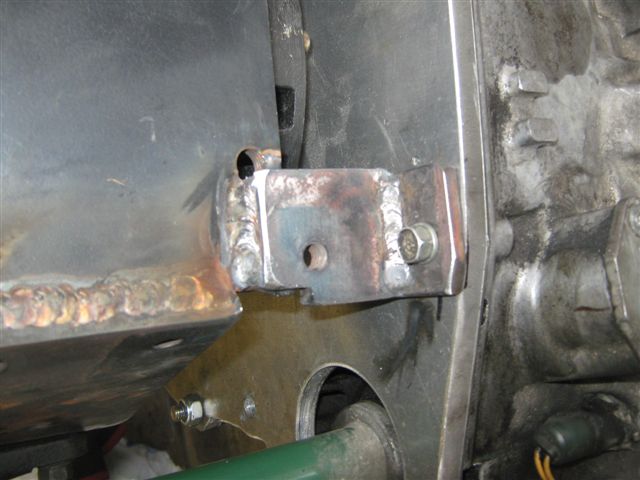 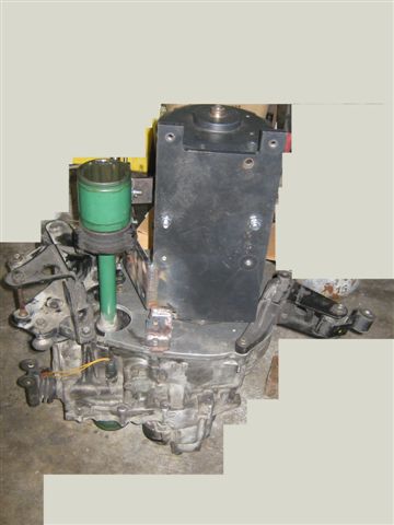 On the following pictures you can see that original engine mountings are installed onto the power plant and everything is ready to be shifted to the engine compartment. 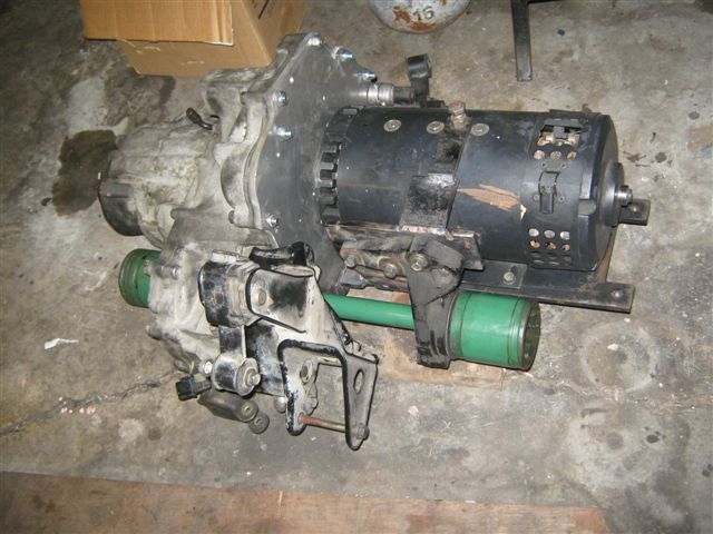 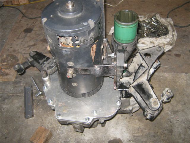 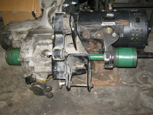 On the picture below the power plant is in the engine bay and the gearbox mountings are all bolted to the car's body the rear of the motor is supported by the jack underneath and supporting mounting is needed to be manufactured. 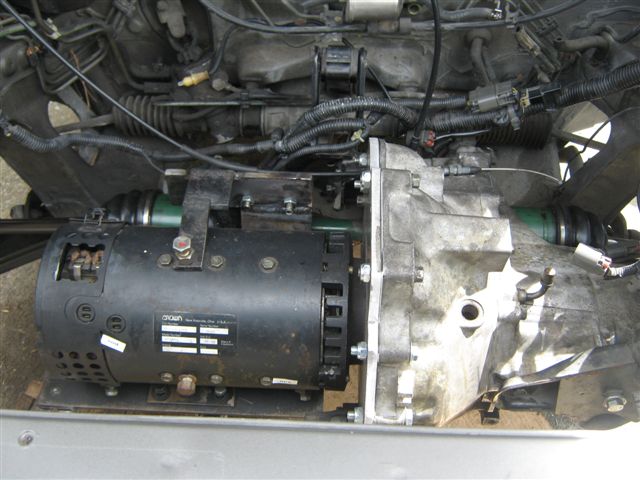 On pictures below you can see the motor plate has an trough like piece of metal already bolted to the plate and the place for the mount welding is prepared. 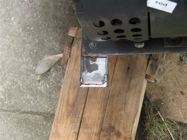  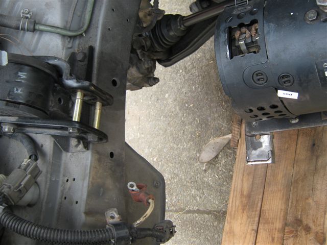 Continue on next page. |